Spar Confusion: Page 13-3, Steps 2 and 3. VAF to the Rescue!

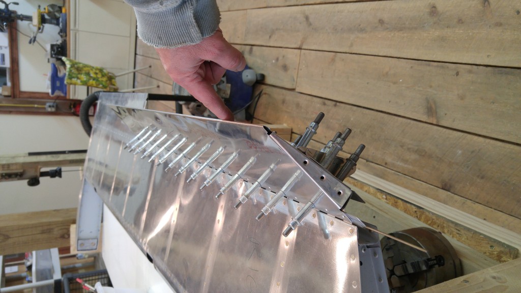
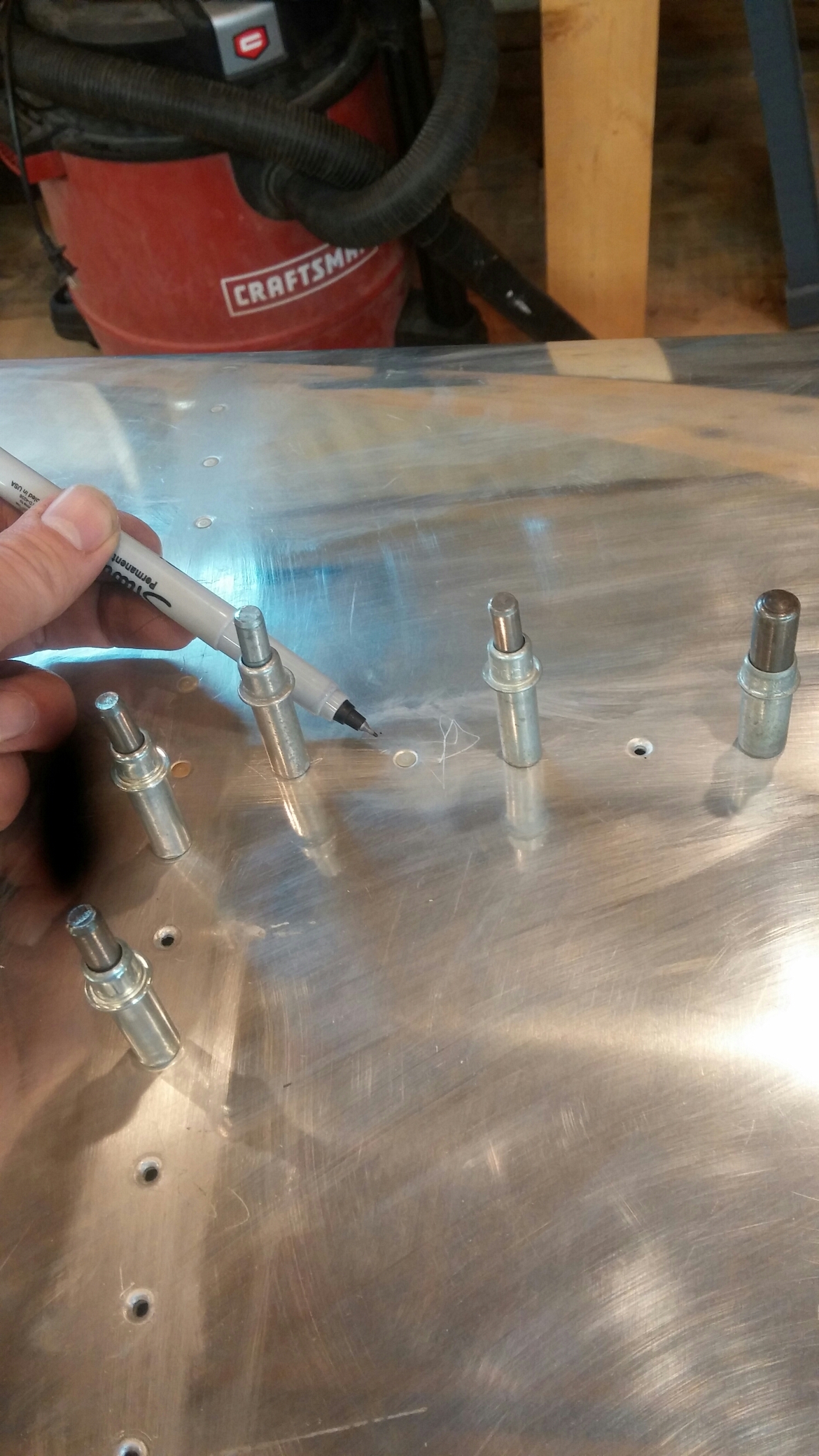
Steps 2 and 3 on Page 13-3 of the RV-10 Wing plans can be rather confusing as to which holes to countersink. The language seems to be rather precise, and if taken literally, has you looking for holes that aren’t there.

The confusing sentence in Step 2 is

“Machine countersink those rib to spar flange attach rivet holes that are in line with the nutplate attach rivet holes and are inboard of the most outboard fuel tank attach nutplate.”

It’s not a difficult sentence to parse, particularly, and the latter third is quite clear. The first half, however, indicates that there should be some (rib to spar flange attach) holes IN LINE with the nutplate rivet holes. Well, if taken literally, there are NO SUCH HOLES. There are some holes that partially fit the description, but they are not exactly in line with the nutplate rivet holes–but their centerlines are about 1/16″ of an inch aft of the nutplate rivet holes’ centerlines. To someone like me who tends to read things very literally, this sentence has the potential to introduce significant confusion and frustration.

I had read aloud and thought about these steps for FAR too long, and finally decided that someone else surely has had the same confusion. So a simple search on Van’s Air Force Forums produced this gem of a thread, which I recommend to anyone as confused as I was.

A link from that thread, provided by Mike Jimenez, contains some helpful photos.
Small Part Paint “Hood”

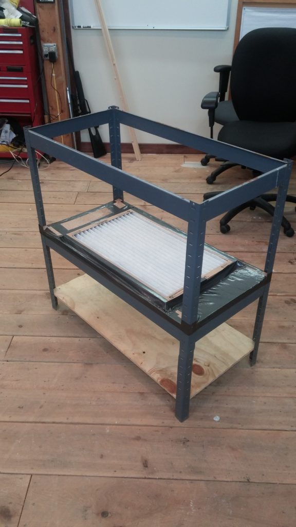
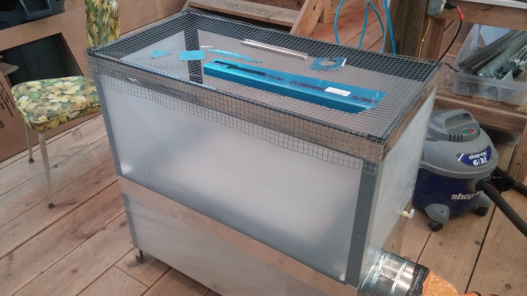
I had an idea for a painting “hood” to capture vapors and paint overspray for use when priming and coating small parts. I’ve seen similar things before, and thought I could make my own rather cost-effectively. At first, I was going to build a frame from scratch, but I realized I had an old metal shelf unit sitting around that I wasn’t using, because the shelves were rather weak particle board.

I figured this could be the basis of my painting hood. I did some brief research on fume hoods and found that best practice for paint booths is a minimum face velocity of 150 ft/min (chemical lab hoods are typically designed for 100 ft/min, go figure…) For this shelf, the open top of which measures 18″ x 36″, the minimum flow required to achieve this face velocity would be 675 ACFM.

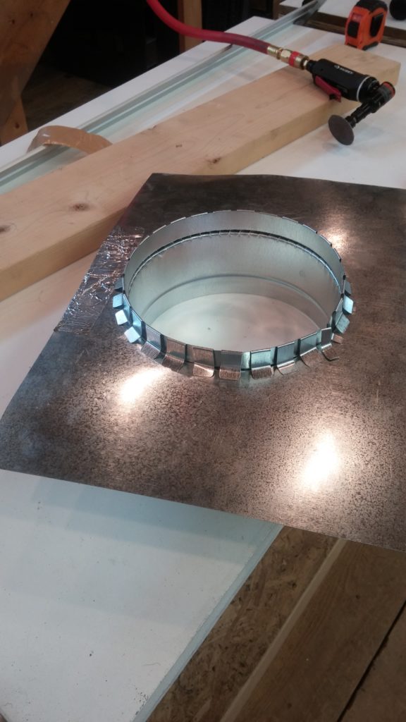
I hopped off to Harbor Freight and bought one of their 8″ ventilators (rated at 1590 CFM, pressure unspecified) and a flexible air duct. The 1590 ACFM should translate into a face velocity of 353 ft/min. Then, I headed over to Home Depot and bought some additional duct pieces and a cheap furnace filter.

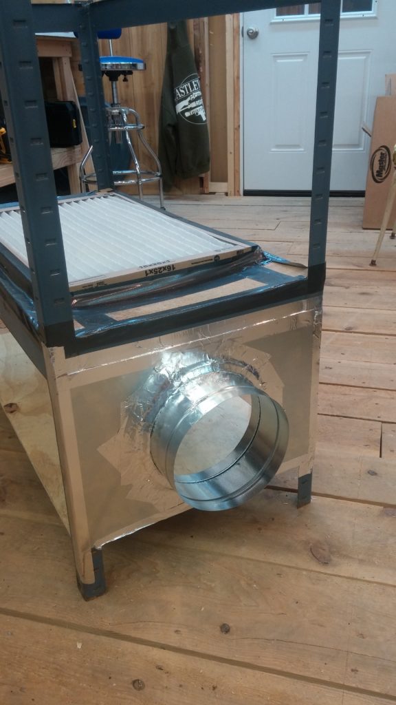
I cut the bottom shelf (which was warped from water damage) to have an opening for the air filter to fit over. Then I duct taped the edges of the hole to provide a better sealing surface. The furnace filter was easily secured to this with duct tape. The furnace filter will operate at an air speed of 572 ft/min.

wpid-20151123_174403.jpg

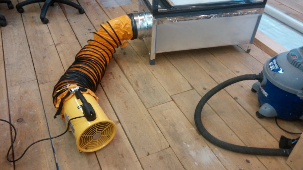
I had some duct tape and heavy (25 mil) plastic sheeting around. These, combined with the parts I had bought, and a small piece of scrap plywood, yielded this:

wpid-20151123_182405.jpgwpid-wp-1448321523309.jpg

wpid-wp-1448323074538.jpg

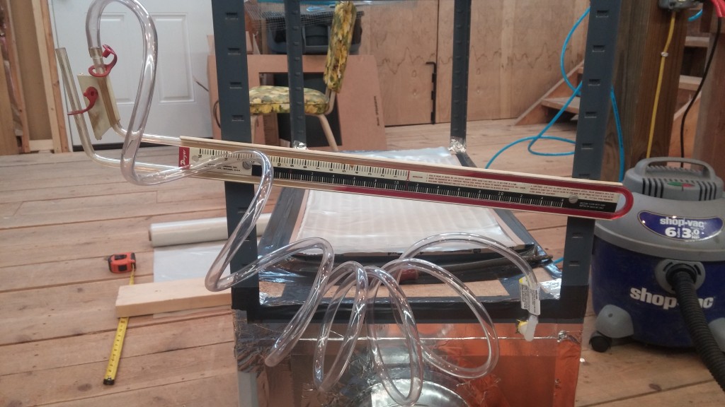
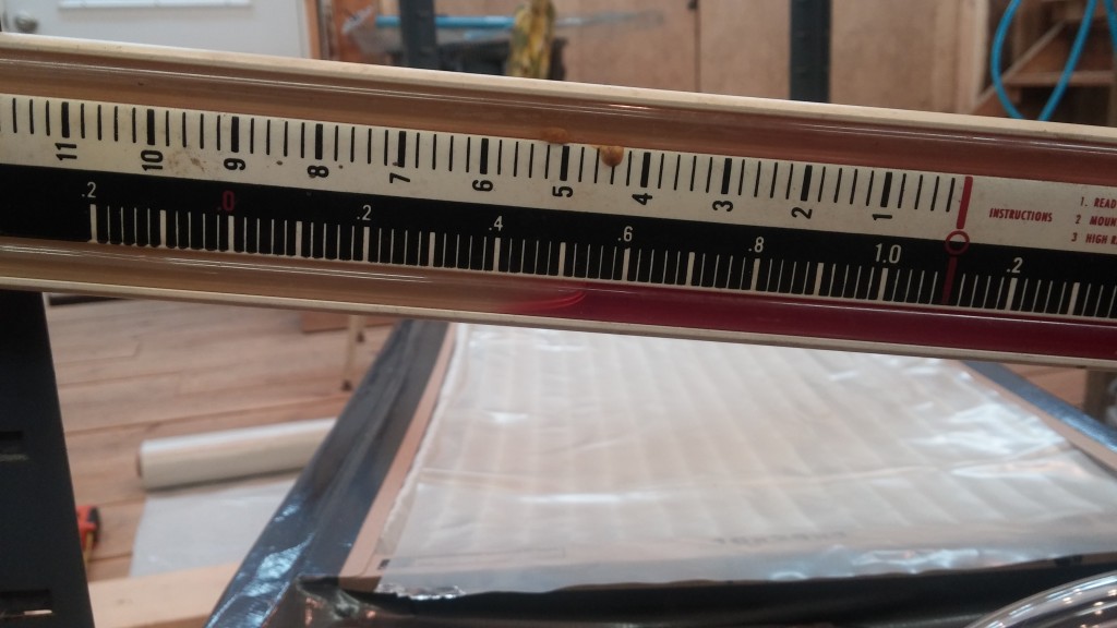
I then added a pressure tap and put my manometer to work. The differential pressure across a clean filter is almost negligible. I then covered the filter mostly with a piece of scrap plastic and the differential pressure across the occluded filter measures 0.52 inches of water column at the high speed setting on the ventilator. It will be interesting to see how much the filter changes from clean to dirty and how well it will work. I may have to use a more expensive filter rated for a smaller particle size for paint and primer.

wpid-20151123_222201.jpgwpid-20151123_222217.jpg

With the dP confirmed, I then finished assembling the unit with more plastic and metallic duct tape. The screen on top should allow for even painting of even small parts.

wpid-20151123_224753.jpg

The ventilator will soon be hooked up to an exhaust duct to pipe fumes out of the workshop. Next step would be to borrow a pitot tube from work that we use to balance dust collector duct work and measure the actual air velocities in the hood and the duct.

Completed Riveting Tailcone Bottom Skin

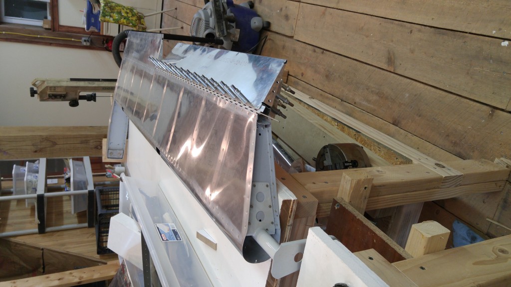
This evening I completed riveting the tailcone bottom skin F-1078 to the side skins F1073-L&R. I used the back riveting technique that others have used with success. My stainless back riveting plate allows 11 rivets to be done simultaneously. I may make a longer back rivet plate if it becomes an issue.

Also riveted F-1055-L&R to the side skins.

I had two rivets that needed to be drilled out and replaced. One required an “oops” rivet.

Time today 3:03. Total time 19:30.

Left Elevator Trim Tab Construction

A time lapse video up to and including drilling and dimpling.  I had an issue at the end with the microstop countersink slipping and I am waiting on some “oops rivets” to arrive to finish it.  I’ll start on the right tab tonight.


[stream flv=x:/www.brunbergs.net/wp-content/uploads/2015/04/lefttrimtab1.240p.flv img=x:/www.brunbergs.net/wp-content/uploads/2015/04/TrimTabShot1-300×169.jpg mp4=x:/www.brunbergs.net/wp-content/uploads/2015/04/lefttrimtab1.mp4 embed=false share=false width=640 height=360 dock=true controlbar=over bandwidth=high autostart=false responsive=16:9 /]